
- Home
- Services
- UFH / Underfloor Heating
- Pipe Loop Drawings
Pipe Loop Drawings
Installer-ready loop layouts with centres, lengths and circuit numbering resolved on the drawing.
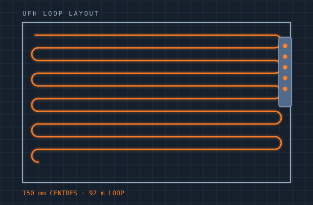
Pipe Loop Drawings
The loop drawing is what the installer holds while kneeling on a screed base. If it does not show pipe centres, circuit numbering, loop length and where the pipe crosses an expansion joint, those decisions get made on site — and the balancing schedule that was calculated for a different layout stops meaning anything.
We draw loops properly. Centres vary within a room where the calculation requires it, typically tightening in the perimeter zone. Loop lengths are kept within the pressure drop limit for the pipe diameter and reported per circuit. Every circuit is numbered to match its manifold port, and pipe crossings at doorways and movement joints are detailed rather than left to improvisation.
Where the room shape makes a clean serpentine impossible — and in real buildings it often does — the layout is resolved on the drawing rather than described in a note.
What you receive
Every item below is issued in your own template, with your layer conventions, title block and revision scheme.
- Loop layout per floor with pipe routing drawn at scale
- Pipe centres annotated per room, including perimeter zone variation
- Loop length and circuit number for every circuit
- Circuit-to-manifold port cross-reference
- Pipe crossing details at doorways, thresholds and movement joints
- Expansion and edge joint positions with pipe sleeving requirements
- Fixing method and spacing notes for the specified system
- Total pipe quantity by diameter for procurement
- Screed depth and cover confirmation per area
Production detail
| Typical turnaround | 24 hours per dwelling floor |
|---|---|
| Pipe centres | 100 / 150 / 200 / 300 mm, varied by zone as calculated |
| Loop length limits | By diameter and pressure drop; typically 80–120 m for 16 mm |
| Layout patterns | Serpentine, counterflow spiral, perimeter-weighted |
| Output formats | DWG, PDF at plot scale, XLSX circuit schedule |
| Revisions | Two rounds included |
Software and formats
We work in your toolchain. If something you use is not listed, ask — the list below is only what we use most.
Frequently asked
Send one pipe loop drawings job and see how we work
Scope, price and programme come back in writing before anything starts. Most first projects are a single deliverable so you can judge us on output, not on a pitch.